1995 Ford Ranger Supercab Logo
Posted on Jun 01, 2009
Answered by a Fixya Expert

Trustworthy Expert Solutions

At Fixya.com, our trusted experts are meticulously vetted and possess extensive experience in their respective fields. Backed by a community of knowledgeable professionals, our platform ensures that the solutions provided are thoroughly researched and validated.

View Our Top Experts

Electrical troubleshooting reset feature locations

Fuel pump in gas tank and headlight,interior light,radio,failure. starter turns motor. electrical wire connection on head light switch shorted.to cause all the above components to fall . after checking fuses in fuse box no fuses were blown. starter turns motor but will not start.

2 Answers

Anonymous

Level 3:

An expert who has achieved level 3 by getting 1000 points

All-Star:

An expert that got 10 achievements.

MVP:

An expert that got 5 achievements.

President:

An expert whose answer got voted for 500 times.

  • Master 2,559 Answers
  • Posted on Jun 01, 2009
Anonymous
Master
Level 3:

An expert who has achieved level 3 by getting 1000 points

All-Star:

An expert that got 10 achievements.

MVP:

An expert that got 5 achievements.

President:

An expert whose answer got voted for 500 times.

Joined: Jan 06, 2009
Answers
2559
Questions
1
Helped
1213015
Points
9283

Look on the right side fender well at the main wiring and you will see a few fuse links,Just look for the one that is swollen or burnt.

Anonymous

Level 1:

An expert who has achieved level 1.

  • Contributor 1 Answer
  • Posted on Jun 13, 2009
Anonymous
Contributor
Level 1:

An expert who has achieved level 1.

Joined: Jun 13, 2009
Answers
1
Questions
0
Helped
350
Points
1

Fuel pump relay is over heating and shutting down the fuel pump

Ad

Add Your Answer

×

Uploading: 0%

my-video-file.mp4

Complete. Click "Add" to insert your video. Add

×

Loading...
Loading...

Related Questions:

0helpful
2answers

Por favor, necesito diagrama de caja de fusibles para Mazda B2300 del 2001

Mazda B-Series (2001) - fuse box diagram Year of production: 2001

Interior fuse panel

Mazda B-Series - fuse box -
interior fuse panel Number Ampere rating [A] Description 1 5 Power Mirror 2 10 Blower Motor Relay, Air Bag Diagnostic Monitor, Passive Deactivation (PAD) Module 3 7,5 Trailer Tow Connector (LH Stop/Turn) 5 10 4×4 Control Module 7 7,5 Trailer Tow Connector (LH Stop/Turn) 9 7,5 Stoplamp Switch 10 7,5 Cruise Control Servo/Amplifier Assy., GEM/CTM, Shift Lock Actuator, Blend Door Actuator, A/C Heater Control Assy., Turn Signals 11 7,5 Instrument Cluster, Main Light Switch, RABS Resistor 13 20 Brake Pedal Position Switch 14 20 RABS Module 10 4WABS Mod., 4WABS Main Relay 16 30 W/W Motor, Wiper Hi-Lo Relay, Wiper Run/Park Relay, Washer Pump Relay 17 25 Cigar Lighter, Data Link Connector (DLC) 19 25 PCM Power Diode, Ignition, PATS 20 7,5 GEM/CTM, Radio 21 20 Flasher 22 20 Auxiliary Power Point 24 7,5 Clutch Pedal Position (CPP) Switch, Starter Interrupt Relay 26 10 Battery Saver Relay, 4×4 Electronic Shift Relay, Interior Lamp Relay, 4×4 Elec. Shift Control Module, Dome/Map Lamp, Instrument Illumination Dimming Module, Restraint Control Module, GEM/CTM, Instrument Cluster 28 7,5 GEM/CTM System, Radio 29 15 Radio 33 15 Headlights, DRL Module, Instrument Cluster 35 15 ISA Horn Relay if not Equipped with Truck Security Module

Engine compartment fuse block

Mazda B-Series - fuse box -
engine compartment Number Ampere rating [A] Description 1 50 I/P Fuse Panel 6 50 ABS Pump Motor 7 30 Powertrain Control Module 8 20 Power Door Locks and Remote Entry 11 50 Starter Relay Ignition Switch 12 10 PCM Memory 13 20 4×4 Motor 16 40 Blower Motor 21 10 PCM Memory 23 20 Fuel Pump Motor 24 30 Headlights 25 10 A/C Clurtch 28 30 4WABS Module 30 15 Trailer Tow 31 20 Fog Lamps, Day Time Running Lamps (DRL) 33 15 Park Lamp 38 10 Left Headlamp Low Beam 41 - Heated Oxygen Sensors 42 10 Right Headlamp Low Beam 45A - Wiper High/Low 45B - Wiper Park/Run 46A 46B - Front Washer Pump 47A 48A - Fog Lamp 48B - Fog Lamp Relay 49 - Full Starter 50A 50B - Fuel Pump 53 - Powertrain Control Module (PCM) Diode 54 - Powertrain Control Module (PCM) Diode 55 - Blower 56A - A/C Clutch Solenoid 56B - Trailer Tow
0helpful
1answer

97 honda cvic dx cranks but wont start and no lights or radio work

Wires,coils,fuel filter,check fuses,relays,battery connection.
1helpful
1answer

2009 chevy aveo ran out of gas now it wont crank

No crank to a mechanic means the starter motor doesn't spin the engine over, is this what you mean? Or do you mean the engine cranks over but will not fire up and run? If it is the latter have you added at least 3 gallons of gas to the tank to make sure the electric fuel pump inside the tank can properly prime? If not do that, also you can spray starting fluid into the engine engine air intake pipe after adding the 3 gallons and see if that gets it going. If it still will not start you have burned up the fuel pump and you will need to drop the fuel tank and replace the pump, remember the pump is cooled and lubricated by the gasoline it runs in, so when you run low on fuel or out you can very quickly severely damage the small electric fuel pump. Never let the gas gauge level go below 1/8 tank to prevent premature fuel pump failure.
3helpful
2answers

Where located fuel sensor Suzuki Ario 2003

Component location diagrams for most 2003 Suzuki Aerio cars and light trucks sold in the U.S. from 1990+.
clsk2003aeri003.gifIgnition System Components Location Diagram for 2003 Suzuki Aerio 2.0 L4 GAS
Components on diagram:
  • TP Sensor
  • Ignition Coil
  • ECM
  • MAF Sensor
  • CMP Sensor
  • clsk2003aeri007.gifElectronic Shift Control System Components Location Diagram for 2003 Suzuki Aerio 2.0 L4 GAS
    Components on diagram:
  • Data Link Connector
  • Transmission Range Sensor
  • Throttle Position Sensor
  • Pressure Control Solenoid Valve
  • Battery
  • clsk2003aeri010.gifInstrument Panel For Connector Layout Diagram Diagram for 2003 Suzuki Aerio SX 2.0 L4 GAS
    Components on diagram:
  • Clutch Switch
  • Thermistor
  • Brake Light Switch
  • Blower Motor Relay
  • Heater Fan Motor
  • clsk2003aeri011.gif
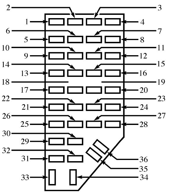
Instrument Panel Harness Diagram for 2003 Suzuki Aerio SX 2.0 L4 GAS
    Components on diagram:
  • Wiper Switch
  • Washer Switch
  • Data Link Connector
  • Turn Signal Relay
  • Radio
  • clsk2003aeri015.gifHeadlight System Location Diagram for 2003 Suzuki Aerio SX 2.0 L4 GAS
    Components on diagram:
  • Headlight Relay
  • Headlight
  • Clearance Light
  • Headlight Diode
  • Clearance Light Relay
  • clsk2003aeri022.gifFuel System Components Diagram for 2003 Suzuki Aerio SX 2.0 L4 GAS
    Components on diagram:
  • Fuel Pump Relay
  • Fuel Tank Pressure Sensor
  • EVAP Canister
  • Fuel Tank Pressure Control Valve
  • Fuel Filler Cap
  • clsk2003aeri027.gifFloor For Single Unit Parts Diagram for 2003 Suzuki Aerio 2.0 L4 GAS
    Components on diagram:
  • Wheel Speed Sensor
  • ABS Control Module
  • G Sensor
  • Air Bag Control Module
  • EVAP Canister Vent Valve
  • clsk2003aeri030.gifInstrument Panel For Ground Point Diagram for 2003 Suzuki Aerio SX 2.0 L4 GAS
    Components on diagram:
  • Instrument Panel Ground Points
  • clsk2003aeri036.gifEngine Compartment For Single Unit Parts Diagram for 2003 Suzuki Aerio 2.0 L4 GAS
    Components on diagram:
  • Throttle Position Sensor
  • Horn Relay
  • Radiator Fan Control Relay
  • Cruise Control Module
  • Condenser Fan Relay
  • clsk2003aeri037.gifEngine Compartment Components Diagram for 2003 Suzuki Aerio SX 2.0 L4 GAS
    Components on diagram:
  • MAP Sensor
  • Knock Sensor
  • Noise Suppressor
  • Heated Oxygen Sensor
  • 2helpful
    1answer

    Fuses panel described in English

    Hope this helps your out. I know the diagram and locator is a bit blurry but hopefully it gets what you need.
    Drivers kick panel:
    Front wiper 20A - Front wiper system Cigar 15A- Cigarette lighter Audio 10A- Audio, remote control mirror Air Bag 10A -Air bag diagnostics Stop lights- 15A -Rear brake light, high mounted stop light ECU B+ 10A - Shift lock actuator, transaxle controle module, radio, engine control module Room 10A - Interior light, clock, ignition key reminder, rear cargo area light switch ABS 10A- Anti lock brake system control unit ECU IG1 10A - Transaxle control module, shift lock actuator, ABS control unit, DRL unit Meter 10A - Instrument panel, back-up switch, electronics time control module, inhibit switch Turn signal 10A- Hazard switch ,front and rear turn lights, turn indicator IGN1 20A - Ignition switch ABS 30A- ABS pump motor TNS 30A- Tail light, license plate light COOL/FAN 30A- Cooling fan Cond/Fan 20A- A/C condenser fan Starter 15A- Start signal , Fuel pump Blower 25A- Blower Motor SR/ACC 10A - Ignition switch Hazard 15A - Hazard and turn signal light D/Lock 25A- Door locks ABS 30A - Anti lock brake system control P/W RH 20A- Power window motor right hand P/W LH 20A- Power window motor left hand IGN2 25A- Ignition Switch
    Engine compartment :
    Head 25A- headlights IG 2 30A- Ignition switch IG coil 15A -Ignition coil, condenser,generator IC regulator, diagnostic connector. O2 down 10A- Rear O2 sensor O2 up 10A- Front O2 sensor Fuel pump 10A -Fuel pump unit Injector 10A -Fuel injector ,camshaft positioning sensor, purge solenoid valve, EVAP, IAC actuator, Mass Airflow sensor, EGR stepper motor. fuel pump relay coil, vehicle speed sensor. A/Con 10A - A/C compressor controls, cooling fan BTN 30A- Brake light , high mounted stop light. Tail light LH 10A- License plate light, tail light , rear combo light, instrument panel illumination Tail light RH 10A-License plate light, tail light , rear combo light, instrument panel illumination Head low 15A- Headlight Head Hi 15A-Headlight Horn 15A- Horn jlmacman.png jlmacman_0.png

    Inside kick panel jlmacman_1.png
    4helpful
    1answer

    What do the symbols on the fuse guide stand for?

    Fuse Locations & Functions
    1. Washer nozzle heaters, glove compartment light (10A).
    2. Turn signal lights (10A).
    3. Fog light relay, instrument panel light dimmer switch (5A).
    4. License plate light (5A).
    5. Comfort system, cruise control, A/C, steering wheel module (7.5A).
    6. Central locking system (5A).
    7. Back-up lights, speedometer vehicle speed sensor (VSS) (10A).
    8. Open
    9. Anti-lock brake system (ABS) (5A).
    10. Engine control module (ECM): gasoline engine (10A)
    11. Instrument cluster, shift lock solenoid (5A).
    12. Data Link Connector (DLC) power supply (7.5A).
    13. Brake tail lights (10A).
    14. Interior lights, central locking system (10A).
    15. Instrument cluster, transmission control module (TCM) (5A).
    16. A/C clutch, after-run coolant pump (10A).
    17. Open.
    18. Headlight high beam, right (10A).
    19. Headlight high beam, left (10A).
    20. Headlight low beam, right (15A).
    21. Headlight low beam, left (15A).
    22. Parking lights right, side marker right (5A).
    23. Parking lights left, side marker left (5A).
    24. Windshield washer pump, windshield wiper motor (20A).
    25. Fresh air blower, A/C (25A).
    26. Rear window defogger (25A).
    27. Motor for rear windshield wiper (15A). (if equipped)
    28. Fuel pump (FP) (15A).
    29. Engine control module (ECM) gasoline engine (15A)
    30. Power sunroof control module (20A).
    31. Transmission control module (TCM) (20A).
    32. Injectors: gasoline engine (10A)
    33. Headlight washer system (20A).
    34. Engine control elements (10A).
    35. 12 V power outlet (in luggage compartment) (30A).
    36. Fog lights (15A). (if equipped)
    37. Terminal (86S) on radio, Instrument cluster (10A).
    38. Central locking system (w/ power windows), Trunk light, fuel door, Trunk lid (15A).
    39. Emergency flashers (15A).
    40. Dual tone horn (20A).
    41. Cigarette lighter (15A).
    42. Radio (25A).
    43. Engine control elements (10A).
    44. Heated seats (15A). (if equipped)

    Fuse arrangements in fuse bracket/battery:
    S162. Glow plugs (coolant) (50A).
    S163. Fuel pump (FP) relay/glow plug relay (50A).
    S164. Coolant fan control (FC) control module/coolant fan (40A).
    S176. Relays panel interior (110A).
    S177. Generator (GEN) (90 Amp.) (110A). Generator (GEN) (120 Amp.) (150A).
    S178. ABS (hydraulic pump) (30A).
    S179. ABS (30A).
    S180. Coolant fan (30A).


    fusecard.jpg
    0helpful
    1answer

    Cigarette lighter fuse

    Hi,

    Here is the fuse relay diagram:

    MKIV FUSE LIST
    1. Washer nozzle heaters, glove compartment light, memory seat control module (10A).
    2. Turn signal lights (10A).
    3. Fog light relay, instrument panel light dimmer switch (5A).
    4. License plate light (5A).
    5. Comfort system, cruise control, Climatronic, A/C, heated seat control modules, automatic day/night interior mirror, control module for multi-function steering wheel, control unit in steering wheel (7.5A).
    6. Central locking system (5A).
    7. Back-up lights, speedometer vehicle speed sensor (VSS) (10A).
    8. Open
    9. Anti-lock brake system (ABS) (5A).
    10. Engine control module (ECM): gasoline engine (10A); diesel engine, Model Year 2000 > (5A).
    11. Instrument cluster, shift lock solenoid (5A).
    12. Data Link Connector (DLC) power supply (7.5A).
    13. Brake tail lights (10A).
    14. Interior lights, central locking system (10A).
    15. Instrument cluster, transmission control module (TCM) (5A).
    16. A/C clutch, after-run coolant pump (10A).
    17. Open.
    18. Headlight high beam, right (10A).
    19. Headlight high beam, left (10A).
    20. Headlight low beam, right (15A).
    21. Headlight low beam, left (15A).
    22. Parking lights right, side marker right (5A).
    23. Parking lights left, side marker left (5A).
    24. Windshield and rear window washer pump, windshield wiper motor (20A).
    25. Fresh air blower, Climatronic, A/C (25A).
    26. Rear window defogger (25A).
    27. Motor for rear windshield wiper (15A).
    28. Fuel pump (FP) (15A).
    29. Engine control module (ECM) gasoline engine (15A); diesel engine (10A).
    30. Power sunroof control module (20A).
    31. Transmission control module (TCM) (20A).
    32. Injectors: gasoline engine (10A); diesel engine (15A).
    33. Headlight washer system (20A).
    34. Engine control elements (10A).
    35. 12 V power outlet (in luggage compartment) (30A).
    36. Fog lights (15A).
    37. Terminal (86S) on radio, Instrument cluster (10A).
    38. Central locking system (with power windows), luggage compartment light, remote/fuel tank door, motor to unlock rear lid (15A).
    39. Emergency flashers (15A).
    40. Dual tone horn (20A).
    41. Cigarette lighter (15A).
    42. Radio (25A).
    43. Engine control elements (10A).
    44. Heated seats (15A).
    Fuse arangements in fuse bracket/battery:
    S162. Glow plugs (coolant) (50A).
    S163. Fuel pump (FP) relay/glow plug relay (50A).
    S164. Coolant fan control (FC) control module/coolant fan (40A).
    S176. Relays panel interior (110A).
    S177. Generator (GEN) (90 Amp.) (110A).
    Generator (GEN) (120 Amp.) (150A).
    S178. ABS (hydraulic pump) (30A).
    S179. ABS (30A).
    S180. Coolant fan (30A). Source(s): http://forums.tdiclub.com/showthread.php?t=122606 fame !
    0helpful
    1answer

    1994 S10 Blazer Tahoe starting problems

    Well, obviously someone didn't tell you the truth because spraying into intake doesn't make the vehicle turn over any better. You have ignition or fuel delivery problem. Start by taking fuel line off at intake and crank engine a couple times catching any gas in a cup or something. If none, then trace fuel line back and under vehicle til you find filter. Should be under driverside midway back on inside of frame. Change this and try test again. If no gas, see if fuel pump is on motor(mechanical pump). Change this and test again. If not on motor then it's in gas tank(electric pump). Most cases the tank has to be lowered to take out pump, careful not to drop, dent or make sparks. Some came with access through the floor so check that first. Normally you can hear an electric pump come on when you turn the key. Good Luck
    0helpful
    2answers

    97 Malibu. V6-3100. Starter turns engine, but car

    I think you may have answered your own question. I would check to see if the fuel pump is turning on when you turn the key on to the run position. You should hear a buzz sound coming from the gas tank. I would start there.
    2helpful
    2answers

    2003 Volkswagen Golf Problem

    it should be number 42


    MKIV FUSE LIST
    1. Washer nozzle heaters, glove compartment light, memory seat control module (10A).
    2. Turn signal lights (10A).
    3. Fog light relay, instrument panel light dimmer switch (5A).
    4. License plate light (5A).
    5. Comfort system, cruise control, Climatronic, A/C, heated seat control modules, automatic day/night interior mirror, control module for multi-function steering wheel, control unit in steering wheel (7.5A).
    6. Central locking system (5A).
    7. Back-up lights, speedometer vehicle speed sensor (VSS) (10A).
    8. Open
    9. Anti-lock brake system (ABS) (5A).
    10. Engine control module (ECM): gasoline engine (10A); diesel engine, Model Year 2000 > (5A).
    11. Instrument cluster, shift lock solenoid (5A).
    12. Data Link Connector (DLC) power supply (7.5A).
    13. Brake tail lights (10A).
    14. Interior lights, central locking system (10A).
    15. Instrument cluster, transmission control module (TCM) (5A).
    16. A/C clutch, after-run coolant pump (10A).
    17. Open.
    18. Headlight high beam, right (10A).
    19. Headlight high beam, left (10A).
    20. Headlight low beam, right (15A).
    21. Headlight low beam, left (15A).
    22. Parking lights right, side marker right (5A).
    23. Parking lights left, side marker left (5A).
    24. Windshield and rear window washer pump, windshield wiper motor (20A).
    25. Fresh air blower, Climatronic, A/C (25A).
    26. Rear window defogger (25A).
    27. Motor for rear windshield wiper (15A).
    28. Fuel pump (FP) (15A).
    29. Engine control module (ECM) gasoline engine (15A); diesel engine (10A).
    30. Power sunroof control module (20A).
    31. Transmission control module (TCM) (20A).
    32. Injectors: gasoline engine (10A); diesel engine (15A).
    33. Headlight washer system (20A).
    34. Engine control elements (10A).
    35. 12 V power outlet (in luggage compartment) (30A).
    36. Fog lights (15A).
    37. Terminal (86S) on radio, Instrument cluster (10A).
    38. Central locking system (with power windows), luggage compartment light, remote/fuel tank door, motor to unlock rear lid (15A).
    39. Emergency flashers (15A).
    40. Dual tone horn (20A).
    41. Cigarette lighter (15A).
    42. Radio (25A).
    43. Engine control elements (10A).
    44. Heated seats (15A).
    Fuse arangements in fuse bracket/battery:
    S162. Glow plugs (coolant) (50A).
    S163. Fuel pump (FP) relay/glow plug relay (50A).
    S164. Coolant fan control (FC) control module/coolant fan (40A).
    S176. Relays panel interior (110A).
    S177. Generator (GEN) (90 Amp.) (110A).
    Generator (GEN) (120 Amp.) (150A).
    S178. ABS (hydraulic pump) (30A).
    S179. ABS (30A).
    S180. Coolant fan (30A).
    Not finding what you are looking for?

    360 views

    Ask a Question

    Usually answered in minutes!

    Top Ford Experts

    ZJ Limited
    ZJ Limited

    Level 3 Expert

    17989 Answers

    Ronny Bennett Sr.
    Ronny Bennett Sr.

    Level 3 Expert

    6988 Answers

    Thomas Perkins
    Thomas Perkins

    Level 3 Expert

    15088 Answers

    Are you a Ford Expert? Answer questions, earn points and help others

    Answer questions

    Manuals & User Guides

    Loading...